Product advantages
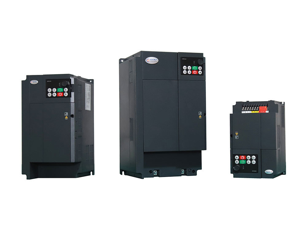
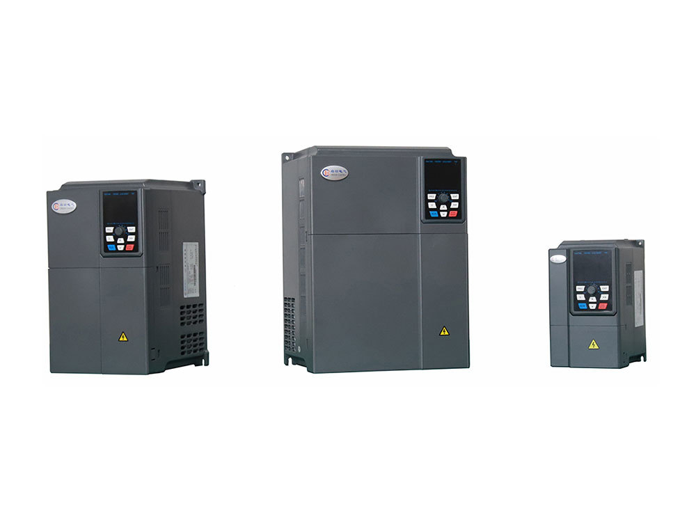
Low voltage variable frequency drive
CGV series variable frequency drive adopts advanced control strategy to realize real high precision flux vector torque control.
Classification:
Key words:
Low voltage frequency converter
Related Annexes:
immediate consultation
Product Description
CGV series variable frequency drive adopts advanced control strategy to realize high-precision magnetic flux vector torque control in the true sense, reaching the industry-leading level, with automatic tuning of motor parameters, zero private service control, speed control, torque control, speed tracking, built-in PLC, built-in PID controller, built-in timer, built-in counter, built-in RS485 communication port, swing frequency control, fixed length control, encoder and given and feedback signal disconnection monitoring and switching, load drop protection, fault signal recall, fault automatic restart, built-in braking unit.
• Core technology: vector control
• High-performance master control system
• Patented pre-charge technology of power cell
• Efficient low voltage debug function
• Flexible automatic intercutting function
• Output waveform self-test function
• Harmonic online analysis and display function
Product Features
More than 20 kinds of fault monitoring, flexible input and output terminals, and up to dozens of main and auxiliary given speed setting methods meet various complex and high-precision transmission requirements, and provide highly integrated integrated solutions for equipment manufacturing customers. The scheme has great value in reducing system costs and improving system reliability, making it a rare integrated driver with excellent control performance in the industry to meet the high-performance requirements of customer applications.
The product has the anti-trip performance beyond similar products and the ability to adapt to harsh power grids, temperature, humidity and dust, which greatly improves product reliability.
Modular design, on the premise of meeting the general needs of customers, can flexibly meet the individual needs of customers and industry needs through extended design, which conforms to the trend of application in the inverter industry.
By optimizing the PWM control technology and the overall design of electromagnetic compatibility, the product meets the environmental requirements of users for low noise and low electromagnetic interference in the application site.
|
Project |
Specifications |
||||
|
Basic |
Maximum frequency |
0~500Hz |
|||
|
Carrier Frequency |
0.5kHz~16kHz; Automatically adjust carrier frequency based on load characteristics |
||||
|
Input frequency resolution |
Digital setting: 0.01Hz |
Analog setting: highest frequency × 0.025% |
|||
|
Control mode |
V/F control |
Open loop vector control (SVC) |
Closed loop vector control (FVC) |
||
|
Starting torque |
0.25Hz/150%(SVC) |
0Hz/180%(FVC) |
|||
|
Speed range |
1: 200(SVC) |
1: 1000(FVC) |
|||
|
Stable speed accuracy |
±0.5%(SVC) |
±0.02%(FVC) |
|||
|
Torque control accuracy |
± 5% above 5Hz (SVC) |
±3%( FVC ) |
|||
|
Overload capacity |
G-type: 150% rated current for 60s |
||||
|
Torque boost |
Automatic torque increase |
Manual torque increase by 0.1%~30.0% |
|||
|
V/F curve |
Linear type |
point-to-multipoint |
Power curve V/F |
V/F separation |
|
|
Acceleration and |
Linear or S-curve acceleration and deceleration methods. Four sets of switchable acceleration and deceleration times, |
||||
|
Dc braking |
DC braking frequency: 0.00Hz~maximum frequency |
||||
|
Inching control |
Jogging frequency range: 0.00Hz~maximum frequency |
||||
|
Simple PLC, |
Up to 16 segments of speed operation can be achieved through built-in PLC or control terminals |
||||
|
Built in PID |
Convenient implementation of closed-loop PID control for process control systems |
||||
|
Automatic Voltage Adjustment (AVR) |
When the voltage of the power grid changes, it can automatically maintain a constant output voltage |
||||
|
Overvoltage, overcurrent, stall control |
Automatically limit the output current and bus voltage of the frequency converter during operation to prevent frequent overvoltage tripping |
||||
|
Fast current limiting |
Minimize overcurrent faults and protect the normal operation of the frequency converter |
||||
|
Torque limitation and control |
Automatically limit torque during operation to prevent frequent overcurrent; Vector control mode can achieve torque control. |
||||
|
Featured features |
Instantly stop without stopping |
During an instantaneous power outage, the reduction in voltage is compensated through load feedback energy to maintain the frequency converter's continued operation for a short period of time |
|||
|
Speed tracking start |
Speed identification of motors under high-speed rotation to achieve smooth start without impact |
||||
|
Fast current limiting |
Fast software and hardware current limiting technology to avoid frequent overcurrent faults in frequency converters |
||||
|
project |
Specifications |
|
|
Featured |
Virtual IO |
Five virtual DOs and five virtual DIs can achieve simple logical control |
|
Timing control |
Timing control function: Set the time range from 0.0Min to 6500.0Min |
|
|
Multi motor switching |
Two sets of independent motor parameters can achieve switching control between two motors |
|
|
Bus support |
One independent MODBUS communication, one CAN communication, one Profibus DP communication |
|
|
Motor overheating protection |
Optional IO expansion card analog input interface can accept motor temperature sensor input (PT100, PT1000) |
|
|
Multi encoder support |
Supports position sensors such as differential, open collector photoelectric encoders, and rotary transformers |
|
|
run |
Command Source |
Operation panel setting, control terminal setting, communication setting. Multiple ways to switch |
|
Frequency source |
10 types of frequency sources: digital setting, panel potentiometer, analog voltage setting, analog current setting, pulse setting, serial communication setting, etc. Multiple ways to switch |
|
|
Auxiliary frequency source |
10 types of auxiliary frequency sources. Flexible implementation of auxiliary frequency fine-tuning and frequency synthesis |
|
|
Input terminal |
Standard: |
|
|
Output terminal |
Standard: |
|
|
Display and |
led display |
Display functional parameters and status information |
|
lcd display |
Optional, display functional parameters and status information in Chinese/English/Russian |
|
|
Parameter copying |
It is possible to display modified parameters, upload and download parameters through LED and LCD keyboards, making it convenient to quickly copy parameters |
|
|
Key locking and function selection |
Implement partial or complete locking of buttons, define the scope of action of some buttons to prevent accidental operation |
|
|
Protection |
Protection function |
Motor short circuit detection to ground, input/output phase loss protection, overcurrent protection, overvoltage protection, undervoltage protection, overheating protection, overload protection, etc |
|
Optional accessories |
Brake components, simple IO expansion card, multifunctional IO expansion card, CAN communication expansion card, differential input PG card, rotary transformer PG card |
|
|
environment |
Place of use |
Indoor, not exposed to direct sunlight, without dust, corrosive gases, flammable gases, oil mist, water vapor, dripping water or salt, etc |
|
altitude |
Below 1000m (between 1000m and 3000m, please reduce the rating for use) |
|
|
ambient temperature |
-10 ℃~+40 ℃ (ambient temperature between 40 ℃~50 ℃, please reduce the rating for use) |
|
|
humidity |
Less than 95% RH, no water droplet condensation |
|
|
vibrate |
Less than 5.9m/s2 (0.6g) |
|
|
storage temperature |
-20℃~+60℃ |
|
Previous Page
Previous Page
Next Page
CGR1000 Series Low Voltage Soft Starter
The CGR1000 series digital soft starter for AC motors can be widely used in loads such as fans, water pumps, conveyors, and compressors.
CGR2000 Series Low Voltage Soft Starter
The CGR2000 series digital AC motor soft starter is a new type of motor starting device with excellent performance.
CGR5100 Series Low Voltage Soft Starter
The CGR5100 series AC motor soft starter is a highly efficient new type of motor starting device.
Immediate consultation
If you are interested in our products, please leave your email, we will contact you as soon as possible, thank you!


